Electric Motor Problems and Solutions

Identifying and addressing the most common electric motor issues is crucial for maintaining efficient and reliable operations. From overheating to bearing failure, understanding the root causes of these problems can help you implement effective solutions.

Common Electric Motor Problems

One of the most prevalent electric motor issues is overheating, which can be caused by a variety of factors, such as overloading, poor ventilation, or a malfunctioning cooling system. By monitoring the motor’s temperature and addressing the underlying causes, you can prevent premature failure and extend the motor’s lifespan.

Bearing failure: Bearing failure can be triggered by improper lubrication, misalignment, or excessive vibration. Implementing a robust maintenance program that includes regular bearing inspections and timely replacements can help mitigate this issue and ensure smooth, uninterrupted operation.

Vibration and Noise: Excessive vibration and unusual noises can be indicative of various problems, such as misalignment, imbalance, or bearing wear. Carefully inspect the motor’s mounting, check for any imbalances, and consider replacing worn-out bearings to resolve these issues.

Reduced Efficiency: If your electric motor is not performing as efficiently as it should, it could be due to factors like a worn-out winding, a faulty capacitor, or a problem with the rotor. Conduct a thorough motor test with Motor Circuit Analysis and/or Electrical Signature Analysis to assess the integrity of the internal components and connections.

Solutions to Resolve Electric Motor Problems

The #1 solution to minimize downtime is to invest in proactive maintenance. 

Regular inspections, cleaning, and monitoring of your electric motors can help identify potential problems before they escalate. From worn bearings to insulation degradation, a trained technician can identify the early warning signs and implement the necessary corrective measures.

By implementing proactive maintenance strategies, such as condition monitoring and predictive maintenance (PdM), you’ll not only enhance the lifespan of your equipment but also drive cost savings and productivity improvements across your operations.

Environment

Maintaining optimal operating conditions and ensuring your motors are not overloaded, properly ventilated, and running at the correct voltage and frequency is a necessity. Neglecting these factors can significantly contribute to premature motor failure.

Condition Monitoring

One of the key steps in preventive maintenance is to conduct regularly scheduled assessments of the facility’s motors and rotating machinery. Closely monitor your motors for signs of wear, such as bearing issues, insulation degradation, and imbalances. 

Scheduled assessments with Motor Circuit Analysis should be conducted to monitor conditions over time. Finding and resolving early stage faults before motor failure can greatly reduce production downtime.

Predictive Maintenance

Implementing a comprehensive predictive maintenance program, including electrical signature analysis, vibration analysis and thermography, provides valuable data to identify potential issues before they arise – empowering businesses to make informed decisions proactively.

Conclusion: Take Control of Your Electric Motor Performance Today

Neglecting preventive maintenance is a common mistake that often leads to premature motor failures, unexpected downtime, and skyrocketing repair costs. 

Investing in preventive maintenance is crucial for prolonging the lifespan and reliability of your electric motors. By addressing issues proactively, you can avoid costly and disruptive breakdowns that can grind your operations to a halt.

Prioritize a proactive maintenance strategy and safeguard the smooth, efficient performance of your electric motors.

READ MORE

3-Phase Motor Fault Finding: A Guide

Electric motors are the backbone of many manufacturing and processing operations around the world. Keeping these motors in good condition and running efficiently should be the number one priority of every business.

3-Phase motors use 3 electric currents to provide power to the internal electrical components, such as the stator, rotor, windings and cabling. When a motor has a problem operating, the components must be analyzed to determine the exact location of the issue to be resolved.

Understanding the Basics of 3-Phase Motor Operation

At the heart of a three-phase motor lies the intricate interplay between the stator and rotor components. 

The stator, composed of three windings, creates a rotating magnetic field when supplied with three-phase alternating current. This rotating field induces a current in the rotor, which in turn generates its own magnetic field. The interaction between these magnetic fields produces the torque that drives the motor’s rotation.

The speed of a three-phase motor is determined by the frequency of the supply voltage and the number of poles in the motor’s design. By adjusting the frequency, operators can precisely control the motor’s speed, enabling fine-tuned control over industrial processes.

Three-phase motors offer several advantages over their single-phase counterparts, including higher efficiency, greater starting torque, and more balanced power distribution. These characteristics make them the preferred choice for a vast array of industrial applications, from pumps and compressors to conveyor belts and cranes.

3-Phase Motor Fault Finding Steps

Diagnosing and resolving issues with 3-phase motors can be a complex task, but with the right tools and techniques, you can efficiently identify and address the root causes of common faults that lead to motor failure.

Visual Examination

First, carefully examine the physical condition of the motor, its connections, and the surrounding environment, we can often uncover obvious issues that may be contributing to the problem.

Analysis of Internal Electrical Components

If there are no obvious damages or issues with the motor and its cabling, the next step is to use specialized testing equipment to measure parameters such as winding resistance, insulation resistance, and current draw. These measurements will provide valuable insights into the motor’s internal health and help us pinpoint any electrical faults.

Mechanical Analysis

Finally, the third phase of our fault finding process involves dynamic testing, where the motor’s performance is observed under load. By monitoring the motor’s speed, vibration, and other operational parameters, we can identify any mechanical issues that may be impacting its efficiency and reliability.

Electric Motor Analysis Tools & Technologies

When it comes to maintaining and troubleshooting 3-phase motors, having the right tools and knowledge is crucial. 

Multimeters

One of the most common instruments used to diagnose motors is a multimeter. 

Multimeters allow you to measure crucial electrical parameters such as voltage, current, and resistance across the motor’s windings. 

However, the measurements of these parameters often overlook faults that can be found with other instruments that measure impedance, inductance, phase angle and current frequency.

Meghommeters

Another common tool used in motor analysis is the megohmmeter. 

A megohmmeter is an electric meter that measures very high resistance values by sending a high voltage signal into the object being tested.

Megohmmeters provide a quick and easy way to determine the condition of the insulation on wire, generators, and motor windings. 

However, megohmmeter insulation testing only detects faults to ground. Because only a portion of motor electrical winding failures begin as ground faults, many motor faults will go undetected using this method alone.

Surge Testing

A surge test subjects the system to voltage spikes on top of the nominal voltage input to determine weaknesses in insulation.

Surge testing should be avoided for motor analysis because it can be destructive to the internal windings.

Motor Circuit Analysis (MCA™)

Motor Circuit Analysis (MCA™) is a non-destructive, deenergized test method to assess the health of a motor.

Initiated from the Motor Control Center (MCC) or directly at the motor itself, this process evaluates the entire electrical portion of the motor system, including the connections and cables between the test point and motor.

[wptb id="12115" not found ]

Electrical Signature Analysis (ESA)

Electrical Signature Analysis (ESA), which encompasses both Motor Voltage Signature Analysis (MVSA) and Motor Current Signature Analysis (MCSA), is an energized test method where voltage and current waveforms are captured while the motor system is running. 

Energized testing provides valuable information for AC induction and DC motors, generators, wound rotor motors, synchronous motors, machine tool motors and more.

Preventive Maintenance to Avoid 3-Phase Motor Failures

Proper preventive maintenance is crucial for avoiding costly 3-phase motor failures. By implementing a proactive approach, you can extend the lifespan of your motors and minimize unplanned downtime.

Condition Monitoring

One of the key steps in preventive maintenance is regular inspections. Closely monitor your 3-phase motors for signs of wear, such as bearing issues, insulation degradation, and imbalances. 

Scheduled assessments of rotating machinery with Motor Circuit Analysis should be conducted to monitor conditions over time. Finding and resolving early stage faults  before motor failure can be imperative to a business’ production.

Environment

Equally important is maintaining optimal operating conditions. Ensure your motors are not overloaded, properly ventilated, and running at the correct voltage and frequency. Neglecting these factors can significantly contribute to premature motor breakdowns.

Predictive Maintenance

Additionally, implementing a comprehensive predictive maintenance program, including electrical signature analysis, vibration analysis and thermography, provides valuable data to identify potential issues before they arise. This data-driven approach empowers businesses to make informed decisions and schedule maintenance proactively.

Conclusion

Because a motor’s intricate components are shielded within, 3-phase fault finding is a tricky but possible task with the right approach and the right tools.

Don’t let 3-phase motor problems catch you off guard. Invest in the right tools and techniques, and you’ll be able to keep your critical equipment running smoothly for years to come.

READ MORE

WYE Start DELTA Run Motor Testing Using Motor Circuit Analysis

Frequently, when a process has a high inertial load, a six lead motor will be used as it can be connected in a WYE configuration while starting to limit current, and then switched to a DELTA configuration automatically by the motor controller once it has come up to speed.

Testing At The Motor Junction Box

As with many motors a simple way to test the six lead motor involves going directly to the motor junction box. After confirming that all Lock Out / Tag Out requirements have been complied with and the motor leads have been checked for the presence of voltage, the motor junction box can safely be opened.
If the motor leads from the controller and the internal motor wires are labeled, make note of that connection. If they are not marked then mark them with colored tape or other identification so that they can be properly reconnected when testing is complete. Disconnect the motor leads from the starter from the internal motor wires, or from the terminals in the box.

The internal motor wires or terminals should be numbered, one through six. As a check, you should be able to test for electrical continuity between terminals/wires 1-4, 2-5, and 3-6. These are your phase wires (A, B, C, or 1, 2, 3).

ATIV
To test the motor with an AT IV you can connect the instrument to terminals/wires 1-4 for phase 1, terminals/wires 2-5 for phase 2, and terminals/wires 3-6 for phase 3. All three windings should have the INS/grd test performed individually.

AT33IND or AT5
To test the motor in the WYE configuration you must short together terminals/wires number 4, 5, and 6. The wires can either be bolted together or significantly sized shorting jumpers used.

The tester(s) can then be connected to terminals/wire numbers 1, 2, and 3. Only one INS/grd test is necessary in this configuration.

Testing At The Motor Controller

There are many different ways to test six lead motor from the motor control depending on the size of the cables and the configuration of the control cabinet. In the cabinet pictured below, using an:

ATIV
At the bottom of the RUN and DELTA contactors do a normal test between 1-4, 2-5, and 3-6. Again, each winding should have the INS/grd test done separately.

AT33IND and AT5
The 4, 5, and 6 leads need to be shorted together. This can either be done with jumpers at the bottom of the DELTA or WYE contactors or the WYE contactor can be somehow forced. With this shorting accomplished the instrument can be connected to cables 1, 2, and 3 at the bottom of the RUN contactor.

READ MORE

What is dissipation factor?

What is dissipation factor?

Dissipation Factor is an electrical test helps defi ne the overall condition of an insulating material.

A di-electric material is a material which is a poor conductor of electricity but an efficient supporter of an electrostatic field. When an electrical insulating material is subjected to an electrostatic field, opposing electric charges in di-electric material form di-poles.Figure of dipoles in dissipation factor.

A capacitor is an electrical device that stores an electrical charge by placing a dielectric material between to conductive plates. The Ground Wall Insulation (GWI) system between the motor windings and the motor frame create a natural capacitor. The traditional method of testing the GWI is to measure the value of the resistance to ground.

This is a very valuable measurement for identifying weaknesses in the insulation but fails to defi ne the overall condition of the entire GWI system.

The Dissipation Factor provides additional information regarding the overall condition of the GWI.

In the simplest form when a dielectric material is subjected to a DC fi eld the diploes in dielectric are displaced and aligned such that the negative end of the dipole is attracted toward the positive plate and the positive end of the dipole is attracted toward the negative plate.

Some of the current that flows from the source to the conductive plates will align the dipoles and create losses in the form of heat and some of the current will leak across the dielectric. These currents are resistive and expend energy, this is resistive current IR. The remainder of the
current is stored on the plates current and will be stored discharged back into system, this current is capacitive current IC.

When subjected to an AC field these dipoles will periodically displace as the polarity of the electrostatic field changes from positive to negative. This displacement of the dipoles creates heat and expends energy.

Simplistically speaking, the currents that displace the dipoles and leaks across the dielectric is resistive IR, the current that is stored to hold the dipoles in alignment is capacitive IC.
Aligned dipole forms from dissipation factor.

Dissipation Factor is the ratio of the resistive current IR to the capacitive current IC, this testing is widely used on electrical equipment such as electric motors, transformers, circuit breakers, generators, and cabling which is used to determine the capacitive properties of the insulation material of the windings and conductors. When the GWI degrades over time it becomes more resistive causing the amount of IR to increase. Contamination of the insulation changes the dielectric constant of the GWI again causing the AC current to become more resistive and less capacitive, this also causes the dissipation factor to increase. The Dissipation Factor of new, clean insulation is usually 3 to 5%, a DF greater than 6% indicates a change in the condition of the equipment’s insulation.

When moisture or contaminants are present in the GWI or even the insulation surrounding the windings, this causes a change in the chemical makeup of the dielectric material used as the equipment’s insulation. These changes result in a change in the DF and capacitance to ground.

An increase in the Dissipation Factor indicates a change in the overall condition of insulation, comparing DF and capacitance to ground helps determine the condition of insulation systems over time. Measuring Dissipation Factor at too high or too low temperature can result in unbalanced results and introduce errors while calculating.

IEEE standard 286-2000 recommends testing at or around ambient temperature of 77 degrees Fahrenheit or 25 degree Celsius.

READ MORE

Stator Looseness Diagnosed by Electric Motor Testing Tool

Initial Findings

A 6.6 kV motor that is used to cool the temperature of gas after going through a gas phase polymerization process at a Petrochemical plant was experiencing abnormal symptoms. A technician conducted a vibration test and noticed an abnormal vibration. Another test was conducted with no load and the abnormal vibration remained. The root cause of the vibration was still undetermined. A team from Instrument Resource Co. in Bangkok Thailand was contacted to investigate the motor further to try and determine the cause of the abnormal vibration.

Motor Circuit Analysis™ (MCA™) was performed using the ALL-TEST PRO 7 PROFESSIONAL™. By performing a series of tests, the AT7™ identified the problem after performing the DYN test function. This particular test is designed to verify stator and rotor integrity and health. This test requires rotating the motor shaft. ALL TEST Pro’s patented Dynamic Stator and Rotor Signature test found there was an imbalance in the Dynamic Stator Signature.

Dynamic Signature Analysis

The Green line is the Stator signature and represents the deviation of the mean values during rotation for each phase. The two black dotted lines represent the Rotor Signature and include an upper and lower signature.

The motor was disassembled. Loose stator slot wedges were found. These loose stator slots were causing the excessive vibration and imbalance in the Dynamic Stator Signature.

After the motor was repaired and reassembled another set of tests were preformed with the AT7™. The subsequent test showed there was no longer an imbalance in the Dynamic Stator Signature representing the stator health was in good condition.

About ALL-TEST Pro, LLC.

ALL-TEST Pro delivers on the promise of true motor maintenance and troubleshooting, with innovative diagnostic tools, software, and support that enable you to keep your business running. We ensure the reliability of motors in the field and help to maximize the productivity of maintenance teams everywhere, backing every ALL-TEST Pro product with unmatched motor testing expertise.

READ MORE

Motor Current Signature Analysis on Gearbox Motor

Introduction

Noise and vibration was investigated on a 7.5 horsepower, 1750 RPM, 575 Vac motor and gearbox using the ALL-TEST PRO™ OL (ATPOL) motor current signature analyzer. One set of data requiring less than one minute of data provided the information necessary. The number of rotor bars, stator slots, bearing information and gears was not available. The lack of information did not hinder the ATPOL in immediately identifying the faults.

Discussion Although lightly loaded, the ATPOL automatically identified casting voids (Figure 1), an electrical fault in the stator (Figure 2), gear problems and identified the number of rotor bars (48) and stator slots (36).

Figure 3 shows the automatic analysis display shown in the ATPOL software.

ALL-TEST PRO™ MD Kit

The ALL-TEST PRO™ MD kit consists of:

  • ALL-TEST PRO™ OL motor current signature analyzer
  • ALL-TEST PRO™ 31 and ALL-TEST IV PRO™ 2000 motor circuit analyzers
  • EMCAT motor management software
  • ATPOL and Power System Manager software modules for EMCAT
READ MORE

Motor Testing: Which Road Will You Take?

Introduction

Allison Transmission, General Motors Corporation is the world leader in design, manufacture and sales of commercial-duty automatic transmissions, hybrid propulsion systems, and related parts and services for on-highway trucks, buses, off-highway equipment and military vehicles. Aside from its primary location in Indianapolis, IN, Allison Transmission, part of GM’s Powertrain Division, has International regional offices in The Netherlands, Japan, China, Singapore and Brazil and is represented in more than 80 countries via its 1500-member distributor and dealer network.

The Total Motor Maintenance (TMM) concept is a strategy that is used every day from motor inventory and delivery, to testing and reliability of motors.


Quality Network Planned Maintenance

Allison Transmission follows the General Motors North American (GMNA) United Auto Workers Quality Network Planned Maintenance (QNPM) process. This program provides a common process and consistent structure to ensure that equipment, machinery, tools and facilities operate in a safe manner and are available to competitively produce the required products to meet customer needs. There are operating principles that define the fundamental direction the QNPM common process takes. These principles were referenced throughout the planning and implementation process to ensure that all activities are focused on achieving the following objectives:

Provide on going support and direction at the GMNA, division, and plant levels

Ensure that manufacturing is the owner and champion of planned maintenance.

Create opportunities for all employees to participate in the process

Implement the operator involvement concept

Pursue proactive maintenance.

Achieve world-class performance in safety, quality, throughput and cost.

Support continuous improvement


There are twelve interdependent elements in planned maintenance that are integral to a successful process. Each element contributes to and provides support for the others. The linked elements, in total, provide the base for the Planned Maintenance Process (Figure 1):

People Involvement and Organization

Financial Monitoring and Control

Spare Parts Availability

Training

Communications

Emergency Breakdown Response

Scheduled Maintenance

Construction Work

Maintenance Tools and Equipment Availability

Reliability and Maintainability

Housekeeping and Cleaning

Production Maintenance Partnership


Supplier Partnership for Motor Program

Commodity Management is the term that Allison Transmission uses for the partnership program with our primary motor supplier. Some of the key features that are realized include improved quality of service and reduced operating and inventory costs. The stored Allison spare inventoried motors are kept at supplier’s warehouse. Subsequently, the supplier meets monthly with Allison personnel and reports on purchases, replacements, delivery time and hard and soft savings (Figure 2).

By using Motor Circuit Analysis (MCA) as one of the technologies (infrared, vibration, ultrasonics, etc.) within the motor program, Allison can more accurately serve our customers’ needs and expectations. Motors can be tested in minutes, even with limited experience, prior to removing and sending them out to a supplier’s motor repair shop. Root cause analysis plays a large role in evaluating the motors with both internal MCA testing and the supplier’s involvement. Upon completion of the motor repair, the supplier supplies Allison with a Repair and a Reason for Repair Report. If the fault is due to contamination, a sample of the contamination found inside the stator windings is collected by the motor shop supplier and passed on to Allison’s technology department for lab analysis. All of this information assists the company in resolving the root cause of the motor problem and failures.

In one department, a servomotor had failed seventeen times in ten months. The supplier was called in to assist in determining a root cause and a corrective action plan. The motor was in a wet harsh area that had a lot of coolant fluid. The vendor suggested a slinger on the motor shaft and a special seal process to keep the motors from prematurely failing. The company’s motor supplier identified these modifications with a yellow stripe to indicate the motor was modified (Figure 3). To date the servomotor has not had another winding failure due to contamination.

This partnership with the motor repair shop has proven to be very effective. Allison has the ability to call 24 hours a day, seven days a week in order to have a stored motor delivered and on its dock within two hours (Figure 4). The response time has been invaluable in planning production schedules. Allison also has access to the motor supplier subject matter experts. As a result, we consider the supplier part of our reliability toolbox. In the end, the motor shop supplier answers to Allison Transmission’s Commodity Management Team, which is comprised of the QNPM rep, electricians from the motor shop and reliability department, the spare parts team, maintenance supervisors and individuals from the finance department.

MCA Overview

Allison Transmission’s motor program is a crucial component within operations. With MCA motors that have problems can be tested to confirm the fault, before being removed and sent out for repair. If a motor problem is not found, the electrician helps the service technician find a root cause. Motors that are difficult to install are tested prior to calling machine repair personnel for installation. Motors in the supplier’s warehouse are audited on a quarterly basis with an MCA test. Some routes have been established due to repetitive motor failures, these motors are tested and trended monthly as part of the MCA process. Motors with pumps are tested prior to rebuilding the pump in order to determine if the motor pump combination may be more economical to replace then to rebuild. The breakdown of the different types of motors repaired or replaced during 2002 can be seen in Figure 4.

QNPM CO CHAMPS OF MAINTENANCE

According to Delbert Chafey, the Allison UAW co-champion, “Using the motor circuit analysis tool has made a tremendous difference in the way we do business in manufacturing services, and the tide has turned regarding losses incurred from making incorrect judgments, for example, deciding a motor is bad and simply replacing it. The ordering of replacement motors from our commodity manager have dropped off dramatically and as a result the manufacturing services organization can provide operations with greater machine uptime. The results are more parts at a more competitive price, a wider technology base, a better use of (Root Cause Failure Analysis) RCFA and a greater level of confidence for our technology group. Greater uptime + savings + trained tradespersons + great tools for our technology toolbox = success. A great combination!”

Terry Bowen, Allison Transmission QNPM co-champion, attended a motor circuit analysis seminar at the 2001 GM QNPM Symposium and believes the company could benefit from implementing an MCA program in the technology department. In May 2001, during a presentation in the motor shop, Bowen acknowledged the importance of the tool and indicated Allison has purchased three.

Prior to purchasing the ALL-TEST Pro™ motor circuit analyzers, analyzing motors involved a lot of guesswork. Occasionally, motors would be sent to a supplier without a complete diagnosis of a problem. After testing by the supplier, a report back would indicate ‘NO PROBLEM FOUND. Now with the MCA program in operations, Allison sees more uptime on machinery and a decrease in ‘NO PROBLEM FOUND’ reports.

Approximately 50 Allison skilled trades personnel are being trained in the application and use of MCA instruments via an internal eight-hour course taught by Dave Humphrey. The trades involved in the training are electricians, powerhouse stationary engineers, air conditioning and maintenance supervisors.

Motor problems

Motor stator faults found by using MCA vary from turn-to-turn, phase-to-phase, coil-to-coil, ground faults, and rotor faults. Rotor faults, which are more common in 4160-volt motors rather than 480 volt, will have broken rotor bars, eccentricity and casting voids. Looking at the phase angle and current frequency on the ALL-TEST ProTM MCA unit can identify stator faults. By comparing the winding resistance of each phase to one another high resistance connections can be seen. Ground faults can be seen by the insulation to ground test. By comparing the impedance and the inductance readings to each other, contamination can be observed and can range from coolant fluid, oil and water to overloaded windings. The contamination on servo motors will start showing their ill effects months prior to failure. The general trend is that there will be service calls indicating an over-current condition on the panel. After going back and tracking work orders through the Allison CMM system, the over current fault will most likely appear more frequently, then requiring a work order to change servo motors. Area planners have received communication alerting them to the over-current condition and how it can be detected before a servomotor has completely failed. Compared to a reactive course of action, planned maintenance provides for cost avoidance. A clean dip and a bake from the motor shop are cheaper and more efficient than a complete rewind.

The applicable cost avoidance spreadsheet is sequentially shared across the QNPM network according to the following:

MCA work order dispatched

Response to the motor site by an electrician

An MCA test is conducted and analyzed and a determination is made

An action plan is implemented. For example, if a servo motor tests good using MCA, a root cause investigation is initiated to check for other causes of the fault such as a blown fuse, SCR, drive, cable or connecter to the motor. If a cable is replaced, a cost comparison between proactive and reactive is documented based upon maintenance history (Table 1).

Allison Transmission prefers proactive vs. reactive maintenance particularly from a financial perspective. For instance, the total cost savings avoidance at Allison attributable to the MCA program in 2002 was $307,664 (Figure 6).

SINGLE PHASE TESTING

When testing three-phase motors, the ALL-TEST Pro™ MCA unit works well when performing comparisons between windings. But what about testing single phase? What, no one uses single phase in industrial applications anymore? Allison uses DC motors, which have a set of field windings (two wires) and the interpoles and armature (two wires) for many applications. The Engineering Test department uses eddy current dynamometers in order to put a simulated load on all manufactured transmissions for testing purposes, which also have 2 sets of windings with just 2 wires. How are these two wire devices compared? First an MCA test on the winding, next store the information in the database along with the nameplate information to identify like motors. Finally, compare like windings and the winding with problems will be revealed. (Table 2).


Case Studies

Figure 7: Testing A Machining Center with MCA


Case Study 1 Infrared Thermography (IR)

An electrician running a predictive IR route noticed a hot motor. The motor was a 7.5 horsepower coolant pump in a group of five identical machines. A work order was submitted for a motor circuit analysis to be conducted and subsequently the MCA was completed and analyzed showing no problems with the motor. A work order for vibration analysis was written, and the results determined that the temperature was driven up due to a bearing fault. The coolant pump was replaced and the temperature was in line with the group of machines. This particular machine is a machining center for transmission cases. When a coolant pump motor fails, historically there would be a loss of production and possible an assembly operation shut down.

Case Study 2: MCA vs DMM & Insulation to Ground Test

An electrician running a predictive IR route noticed a hot 5 horsepower motor on a machine with 4 drill heads that performs a drilling operation. The MCA was performed and analyzed and by comparing the impedance and inductance readings, which were clearly not in parallel, the results showed the motor windings were contaminated. Impedance nor inductance cannot be seen with a DMM or an insulation to ground tester. Both the resistance and the insulation to ground test were good. The motor was sent for repairs as this model is not available in the warehouse. MCA was performed to determine the reason why the motor had this contamination. The motor shop did a full autopsy on the motor, and, after cracking open the end bells it was obvious that the problem was fluid in the windings. The unknown liquid was poured into a sample bottle. The motor shop did extensive repairs on the windings, and also applied an epoxy seal to the area after determining the liquid to be a mix of coolant and hydraulic oil. The motor was returned and installed in less than 24 hours. This machine drills a series of holes on the carrier for the transmission. If the machine had run to complete failure, it would have shut down the assembly line. Ordering estimates on a new motor were three days.

Case Study 3 # 8 Air Compressor, 4160 volt 1000 horsepower

On June 18, 2003 the power house tradesmen provided data to the reliability department for review and clarification of ALL-TEST IV PRO™ 2000 readings on the 4160-volt, 1,000-horsepower motor on #8 air compressor. A resistive unbalance of 84.5% was found. The motor was tested at the MCC then at the motor connection lugs. The bad connection at the lugs was found and corrected, reducing the unbalance to 0.17%. This case again showed that MCA is useful, as the 4160-volt connections at the compressor did not have to be taken apart and put back together. The motor did not have to be removed and sent to the motor shop supplier, McBroom Electric. This saved the cost of an unnecessary motor repair and the loss of compressed air for some of the production machines.

Conclusion

Motor Circuit Analysis has made an impact here at Allison. With the NFPA 70E PPE issues approaching, off line motor circuit analysis is very valuable and safe. The motor world will now perhaps be viewed differently from the days of just using a multi-meter and an insulation-to-ground tester. Allison Transmission believes and trusts systems that consistently and correctly allows for proactive maintenance.


About the Author

Dave Humphrey is an eighteen-year veteran journeymen electrician with General Motors. His father is an electrical contractor and Dave started working with his father at age 10. He worked for a variety of contractors prior to going to GM. Dave is certified in motor circuit analysis, infrared thermograph and vibration analysis. Has attended numerous classes on motor diagnostics, ultrasound and root cause analysis. Dave is a graduate of Purdue University and a Certified Master Electrician. Dave has taught motors, transformers, troubleshooting techniques and the National Electrical Code in the GM apprenticeship program. Presently Dave teaches motor circuit analysis classes at Allison. Dave is a Vice President of Habitat For Humanity in his county and provides electrical wiring for all the homes in the program. Dave is a very active family man and Christian.

READ MORE

Polarization Index Testing on Electric Motors Now Surpassed by Modern Methods

Regarding electric motor testing, polarization index (PI) is a measure of how much the insulation system resistance improves (or degrades) over time.

While the PI Test has been considered the primary test when evaluating the condition of a motor’s insulation, its process has become outdated compared with newer testing methods that provide a more comprehensive diagnostic evaluation of a motor’s overall health.

This article provides a practical understanding of a motor’s insulation system, a basic understanding of polarization index testing, and how modern motor testing methods provide more comprehensive results in less time.

POLARIZATION INDEX (PI)

The polarization index (PI) test is a standard electric motor testing method developed in the 1800s that attempts to determine the health of a motor’s winding insulation.

While the PI test provides information on ground wall insulation (GWI) systems typically installed prior to the 1970s, it fails to provide an accurate condition of the winding insulation in modern motors.

PI testing involves applying DC voltage (typically 500V – 1000V) to the motor’s winding to measure the effectiveness of the GWI system to store an electrical charge.

Since the GWI system forms a natural capacitance between the motor windings and the motor frame, the applied DC voltage will be stored as an electrical charge the same as any capacitor.

As the capacitor becomes fully charged, the current will decrease until all that remains is the final leakage current, which determines the amount of resistance the insulation provides to ground.

In new, clean insulation systems, the polarization current decreases logarithmically with time as the electrons are being stored.  The Polarization Index (PI) is the ratio of the insulation resistance to ground (IRG) value taken at 1 and 10-minute intervals.

PI = 10 Minute IRG/1 Minute IRG

On insulation systems installed pre-1970s, PI testing occurs while the dielectric material is being polarized.

If the ground wall insulation (GWI) begins to degrade, it undergoes a chemical change causing the dielectric material becoming more resistive and less capacitive, lowering the dielectric constant and reducing the ability of the insulation system to store an electrical charge. This causes the polarization current to become more linear as it approaches the range where leakage current is predominate.

However, on newer insulation system post 1970’s, for various reasons the entire polarization of the dielectric material occurs in less than one minute, and the IRG readings are above 5,000 Meg-ohms. The calculated PI may not be meaningful as an indication of condition of the ground wall indication.

Additionally, since this test creates the electrostatic field between the windings and the  motor frame it provides very little if any indication of the condition of the winding insulation system. The best indication of these types of faults through the use of MCA measurements of phase angle and the current frequency response.

INSULATING MATERIALS

In electric motors, insulation is the material that resists the free flow of electrons, directing the current through a desired path and preventing it from escaping elsewhere.

In theory, the insulation should block all current flow, but even the best insulating material allows a small amount of current to pass through. This excess current is commonly referred to as leakage current.

While it is generally accepted that motors have a 20-year life span, failure of the insulating system is the primary reason electric motors fail prematurely.

The insulating system begins to degrade when the insulation becomes more conductive due to a change in its chemical composition. The insulation’s chemical makeup changes over time from gradual use and/or other damages. The leakage current is resistive and creates heat which results in additional and more rapid degradation of the insulation.

Note: Most enameled wires are engineered to guarantee a service life of 20,000 hours at rated temperatures (105 to 240° C).

INSULATION SYSTEMS

Motors and other electrical equipment with coils have 2 separate and independent insulating systems.

Ground wall insulation systems separate the coil from the frame of the motor, preventing voltage supplied to the windings from escaping to the stator core or any part of the motor frame. Breakdown of the ground wall insulation system is called a ground fault and creates a safety hazard.

Winding insulation systems are layers of enamel that surround the conducting wire that provides current to the entire coil to create the stator magnetic field. Breakdown of the winding insulation system is called a winding short and weakens the coil’s magnetic field.

INSULATION RESISTANCE TO GROUND (IRG)

The most common electrical test conducted on motors is the insulation resistance to ground (IRG) test or “spot test”.

By applying DC voltage to the motor winding, this test determines the point of minimum resistance the ground wall insulation presents to the motor frame.

CAPACITANCE

Capacitance (C), measured in Farads, is defined as the ability of a system to store an electrical charge. Establishing the capacitance of a motor is found by using the equation: 1 Farad = the amount of stored charge in coulombs (Q) divided by the supply voltage.

Example:  If applied voltage is a 12V battery and the capacitor stores .04 coulombs of charge it would have a capacitance of .0033 Farads or 3.33 mF. One coulombs of charge is approximately 6.24 x 10¹⁸ electrons or protons. A 3.33 mF capacitor would store approximately 2.08 X 10¹⁶ electrons when fully charged.

Capacitance is created by placing a dielectric material between conductive plates. In motors, ground wall insulation systems form a natural capacitance between the motor windings and motor frame. The winding conductors form one plate and the motor frame forms the other, making the  ground wall insulation the dielectric material.

The amount of capacitance depends on:

The measured surface area of the plates – Capacitance is directly proportional to the area of the plates.

The distance between the plates – Capacitance is inversely proportional to distance between the plates.

The dielectric constant – Capacitance is directly proportional to the dielectric constant

CAPACITANCE TO GROUND (CTG)

The capacitance-to-ground (CTG) measurement is indicative of the cleanliness of the windings and cables of a motor.

Because the ground wall insulation (GWI) and the winding insulation systems form a natural capacitance to ground, each motor will have a unique CTG when the motor is new and clean.

If the motor windings or GWI become contaminated, or the motor has moisture ingression, the CTG will increase. However, if either GWI or the winding insulation undergoes thermal degradation, the insulation will become more resistance and less capacitive causing the CTG to decrease.

DIELECTRIC MATERIAL

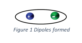
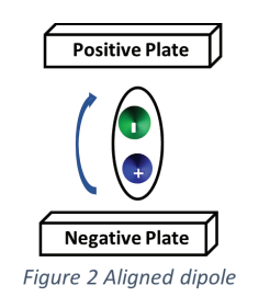
A dielectric material is a poor conductor of electricity but supports an electrostatic field. In an electrostatic field, electrons do not permeate the dielectric material and positive and negative molecules pair to form dipoles (pairs of oppositely charged molecules separated by distance) and polarize (the positive side of the dipole will align towards the negative potential and the negative charge will align towards the negative potential).

DIELECTRIC CONSTANT (K)

A dielectric constant (K) is a measure of a dielectric material’s ability to store an electrical charge by forming dipoles, relative to a vacuum which has a K of 1.

The dielectric constant of insulating material is dependent on the chemical makeup of the molecules combined to form the material.

The K of a dielectric material is affected by the material’s density, temperature, moisture content, and the frequency of the electrostatic field.

DIELECTRIC LOSS

An important property of dielectric materials is the ability to support an electrostatic field, while dissipating minimal energy in the form of heat, known as dielectric loss.

DIELECTRIC BREAKDOWN

When voltage across a dielectric material becomes too high causing the electrostatic field to become too intense, the dielectric material will conduct electricity and is referred to as dielectric breakdown. In solid dielectric materials, this breakdown may be permanent.

When dielectric breakdown occurs, the dielectric material undergoes a change in its chemical composition and results in a change in the dielectric constant.

CURRENTS EMPLOYED WITH A CHARGING CAPACITOR

Several decades ago, the polarization index test (PI) was introduced to evaluate the ability of the insulation system to store an electrical charge. Since there are essentially three different currents, as described above, involved in charging a capacitor.

Charging Current – The current accumulated on the plates and depends on the area of the plates and the distance between them. The charging current usually ends in < than 1 minute. The amount of charging will be the same regardless of the condition of the insulating material.

Polarization Current – The current required to polarize the dielectric material, or align the diploes created by placing the dielectric material in an electrostatic field. Typically with the insulation systems installed in motors (pre-1970s) when the polarization index testing was developed the nominal value of a new, clean insulation system would be in the 100’s of megaohm (106) range and would typically require more than 30 minutes and in some cases many hours to complete. However, with a newer insulation system (post-1970s) the nominal value of a new, clean insulation system will be in the giga-ohm to tera-ohm (109, 1012)  and typically fully polarizes before the charging current fully finishes.

Leakage Current – The current that flows across the insulating material and dissipates heat.

CHARGING CURRENT

An uncharged capacitor has plates that share an equal number of positive and negative charges.

Applying a DC source to the plates of an uncharged capacitor will cause electrons to flow from the negative side of the battery and accumulate on the plate connected to the negative post of the battery.

This will create an excess of electrons on this plate.

Electrons will flow from the plate connected to the positive post of the battery and flow into the battery to replace the electrons accumulating on the negative plate. Current will continue to flow until the voltage on the positive plate is the same as the positive side of the battery and the voltage at the negative plate will achieve the potential of the negative side of the battery.

The number of electrons displaced from the battery to the plates depends on the area of the plates and the distance between them.

This current is referred to as the charging current, which does not consume energy and is stored in the capacitor. These stored electrons create an electrostatic field between the plates.

POLARIZING CURRENT

Placing a dielectric material between the plates in a capacitor increases the capacitance of a capacitor relative to the spacing between of plates in a vacuum.

When a dielectric material is placed in an electrostatic field, the newly formed dipoles will polarize, and the negative end of the dipole will align with the positive plate and the positive end of the dipole will align towards the negative plate. This is referred to as polarization.

The higher the dielectric constant of a dielectric material, the greater number of electrons are required, thereby increasing the capacitance of the circuit.

LEAKAGE CURRENT

The small amount of current that flows across the dielectric material while still maintaining its insulating properties is referred to as the effective resistance. This is different than the dielectric strength which is defined as the maximum voltage that a material can withstand without failing.

As an insulating material degrades, it becomes more resistive and less capacitive, increasing leakage current and decreasing the dielectric constant. The leakage current produces heat and is considered a dielectric loss.

DISSIPATION FACTOR

Is an alternative test technique that uses an AC signal to exercise groundwall insulation (GWI) system. As explained above using a DC signal to test the GWI 3 different currents are encountered, however, the instrument is unable to differentiate the currents other than the time. However, by applying an AC signal to test the GWI it is possible to separate the currents that are stored (charging current, polarization current) from the resistive current (leakage current).

Since both the charging and polarization currents are stored currents and are returned to the on the opposing ½ cycle the current leads the voltage by 90°, whereas the leakage current which is a resistive current that dissipates heat and the current is in-phase with the applied voltage. The dissipation factor (DF) is simply the ratio of the capacitive current (IC) to the resistive current (IR).

DF = IC / IR

On clean, new insulation typically the  IR is < 5% of the IC, if the insulating material becomes contaminated or degrades thermally either the IC decreases or the IR increases. In either case the DF will increase.

MOTOR CIRCUIT ANALYSIS (MCA)

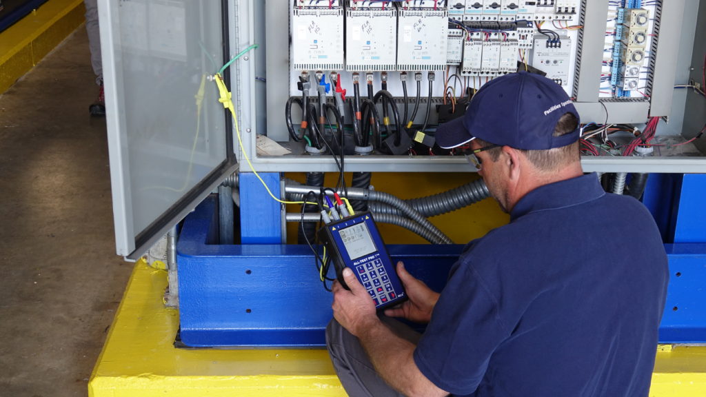
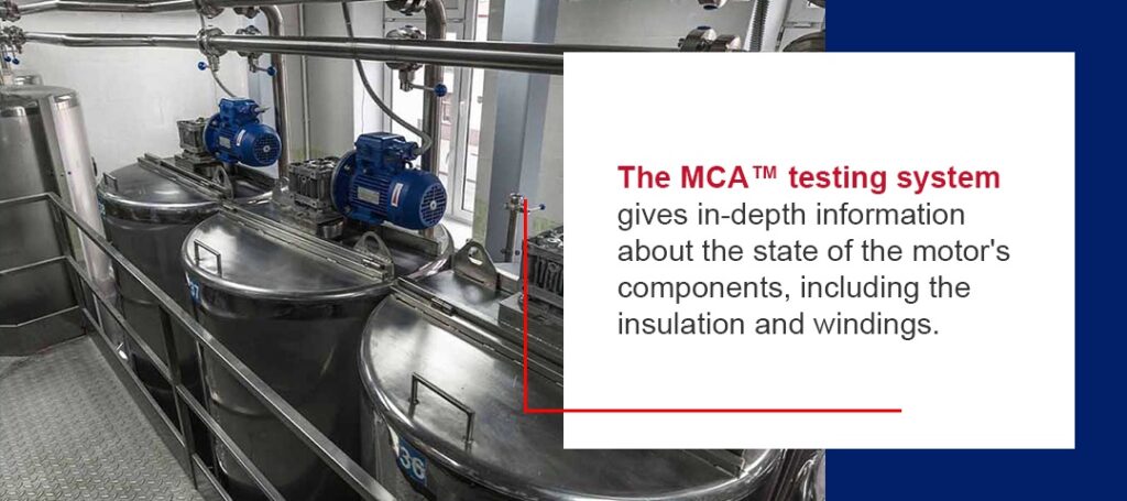
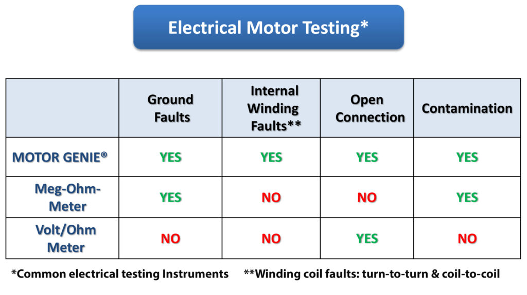
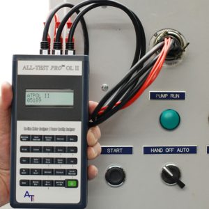
Motor Circuit Analysis (MCA™), also referred to as motor circuit evaluation (MCE), is a deenergized, non-destructive test method used to assess the health of a motor. Initiated from the Motor Control Center (MCC) or directly at the motor itself, this process evaluates the entire electrical portion of the motor system, including the connections and cables between the test point and motor.

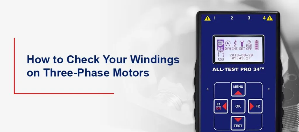
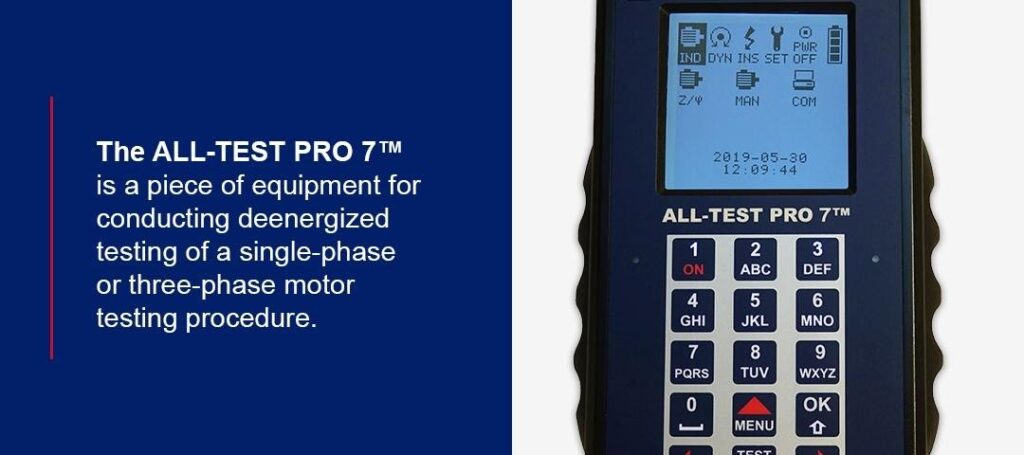
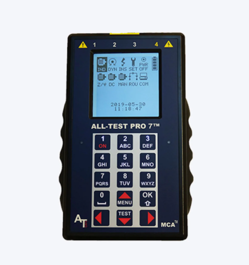
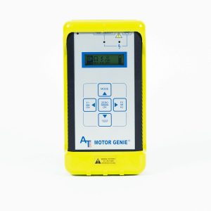
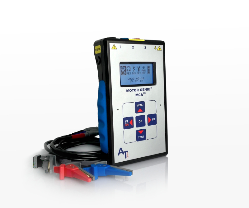
While the motor is off and unpowered, tools such as the AT7 and AT34 by ALL-TEST Pro, use MCA to assess:

  • Ground Faults
  • Internal Winding Faults
  • Open Connections
  • Rotor Faults
  • Contamination

Motor testing using MCA™ tools is very easy to implement, and the test takes less than three minutes, compared to polarization index testing typically taking over 10 minutes to complete.

HOW DOES IT MOTOR CIRCUIT ANALYSIS WORK?

The electrical portion of the three phase motor system is made up of resistive, capacitive and inductive circuits. When a low voltage is applied, healthy circuits should respond in a specific way.

ALL-TEST Pro Motor Circuit Analysis tools apply a series of low-voltage, non-destructive, sinusoidal AC signals through the motor to measure the response of these signals. This deenergized test takes only a few minutes and can even be performed by an entry-level technician.
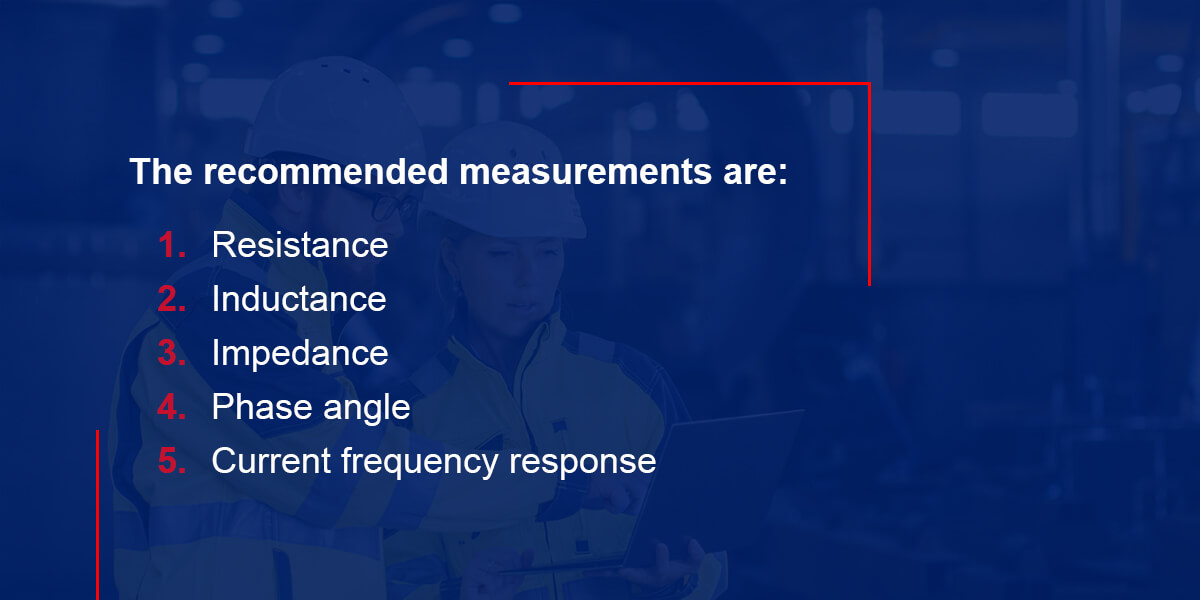
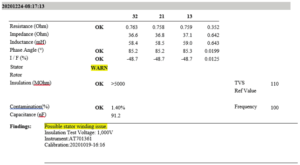
MCA measures:

  • Resistance
  • Impedance
  • Inductance
  • Fi (phase angle)
  • Dissipation Factor
  • Insulation to Ground
  • I/F (current frequency response)
  • Test Value Static (TVS)
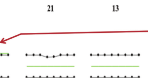
  • Dynamic Stator and Rotor Signatures

And applicable on:

  • AC/DC Motors
  • AC/DC Traction Motors
  • Generators/Alternators
  • Machine Tool Motors
  • Servo Motors
  • Control Transformers
  • Transmission & Distribution Transformers

SUMMARY

During the 1800s, the polarization index test was an effective method of determining a motor’s overall condition. It has become less effective, however, with modern insulation systems.

While the PI test is time-consuming (15+ minutes) and unable to determine if the fault is in the winding or groundwall insulation, modern technologies, such as MOTOR CIRCUIT ANALYSIS (MCATM), identify connection issues, turn-to-turn, coil-to-coil, and phase-to-phase developing winding faults in very early stages with tests completed in under 3 minutes.

Other technologies, such as DF, CTG & IRG, provide a condition of the groundwall insulation system in tests completed in minimal time as well.

By combining new technologies, such as MCA, DF, CTG, and IRG, modern electric motor testing methods provide a much more comprehensive and thorough evaluation of an entire motor’s insulation system quicker and easier than ever before. READ MORE

Why Testing an Electric Motor with a Multimeter Is Not Enough

When an electric motor fails to start, runs intermittently, runs hot, or continually trips its overcurrent device, there my be a variety of causes, however many technicians and repairmen tend to conduct electric motor testing with multimeters or megohmmeters alone.

Sometimes the motor’s issue is the power supply, including branch circuit conductors or motor controller, while other possibilities include mismatched or jammed loads. If the motor itself has developed a fault, the fault may be a burnt wire or connection, a winding failure, insulation deterioration, or a deteriorating bearing.

Testing an electric motor with a multimeter provides an accurate diagnosis of the electrical power supply going in and out of the motor, but does not identify the specific issue to fix.

Testing the motor’s insulation with a megohmmeter alone only detects faults to ground.

Since approximately less than 16% of motor electrical winding failures begin as ground faults, other motor issues will go undetected using a megohmmeter alone. 

Moreover, surge testing of an electric motor requires high voltages to be applied to the motor. This method can be destructive when testing a motor, making it an unsuitable method for troubleshooting and true predictive maintenance testing.

Testing an electric motor with a multimeter does not provide comprehensive diagnosis like the All-TEST Pro 7.

Electric Motor Testing with a Multimeter vs the ALL-TEST Pro 7

A number of diagnostic tools available on the market today – a clamp-on ammeter, temperature sensor, megohmmeter, multimeter, or oscilloscope – may help illuminate the problem, but only one electric motor testing brand develops comprehensive, hand-held devices that not only analyze all of the aspects of the forementioned devices but accurately pinpoints the exact fault of the motor to be repaired.

[wptb id="13909" not found ]

ALL-TEST Pro devices offer more complete motor testing than any other options on the market.

Our instruments go above and beyond normal testing equipment for accurate, safe, and fast motor testing.

Save money and time by proactively detecting developing faults before they cause irreversible motor failures.

VIEW THE ALL-TEST PRO 7

READ MORE

Improving Electrical Reliability by Implementing Motor Circuit Analysis

When you want to determine the health of your motor, Motor Circuit Analysis (MCA™) is a preferred choice in any industry. This deenergized motor testing method allows you to gauge the entire health of your motor, transformer, generator, and other coil-based equipment in just a few minutes. MCA’s thoroughness helps you determine a motor system’s electrical health and increase your equipment’s electrical reliability.

What Is MCA?

Motor Circuit Analysis is an impedance based measurement technology that injects a Non-destructive low voltage AC sinusoidal signal through the motor winding system that exercises the entire motor insulation system to identify any unbalances in the windings that would indicate either a current or potential motor fault. In a perfectly healthy electric motor all three phases will be identical to each other meaning all measurements acquired will also be identical. A deviation of measurements between phases signifies a developing or current fault.

MCA allows the user to quickly analyze and identify the following motor faults:

  • Ground Faults – Measure the resistance between motor’s winding system and the motor frame (ground) to determine if the motor is safe to run. This value is typically measured in Megaohms (Mohms).
  • Rotor Faults – Rotor faults are determined my measuring the impedance values of all three windings as the rotor rotates in the magnetic field of the stator. Typical rotor faults are broken or fractured rotor bars and casting voids that develop during rotor manufacturing. These faults are typically not seen by eye so they will go unseen until catastrophic failure occurs unless proper testing strategies are utilized.
  • Internal Winding Shorts – Motor Circuit Analysis is capable of determining early stage turn to turn, coil to coil, and phase to phase internal winding shorts. Being able to determine these faults is what separates Motor Circuit Analysis from conventional motor testing practices. These faults develop as slight changes to the chemical makeup of the winding insulation material which means standard resistance readings will not detect these changes until a direct short between two conductors is made and a catastrophic failure occurs.

You can initiate MCA directly from the motor or at the Motor Control Center (MCC). By testing from the MCC, you can evaluate the entire motor system such as the motor starter or drive, motor cables and connections between the motor and test point. This testing method stands out from the competition, as no other motor testing technology has these capabilities and because MCA injects a low voltage signal into the motor circuit there is no need to disconnect a Variable Frequency Drive (VFD). MCA’s in-depth testing helps you easily spot errors and quickly take action to increase electrical reliability.

How Does MCA Work and Increase Electrical Reliability?

How Does MCA Work and Increase Electrical Reliability?

Test Value Static

One of the main elements of MCA solutions is the Test Value Static (TVS), which helps you maintain electrical reliability in your motor. A motor’s TVS is essential, as it lives with the motor from the cradle to the grave and can help you spot issues that could cause poor electrical reliability. MCA calculates a motor’s TVS by taking measurements on all three phases of a motor. After taking these measurements, they’re put through a proprietary algorithm that produces a single number.

Reference Value Static

When a baseline test is taken on a new or recently repaired motor, the TVS value is referred to as the Reference Value Static (RVS). This value lives with the motor until it fails and is commonly referred to in future tests. With MCA, you can then compare the baseline RVS and a new TVS. If these values show a deviation of over 3%, a fault is likely developing, meaning you should troubleshoot further.

By quickly calculating RVS and TVS and comparing the results, MCA systems help you increase electrical reliability. When your readings show higher-than-acceptable deviations, you can make repairs before the motor’s electrical reliability is severely impacted.

MCA Software

Another way MCA equipment helps improve electrical reliability is through its incorporation of software. MCA software allows you to create a route that guides you to the most critical motors at your facility to prevent unnecessary downtime and save money.

MCA can detect developing turn to turn, coil to coil and phase to phase faults before any other motor testing technology. By detecting these faults, the software allows you to make a maintenance and repair plan to protect your motor’s electrical reliability and prevent failure.

Motor testing software also allows users to efficiently organize test records and trend results over time. With historical records, you can more easily determine when equipment’s health is decreasing and has the potential to fail — ensuring your motors deliver consistent electrical performance.


MCA Testing Applications

MCA testing has many applications designed to check your motor’s electrical health and ensure everything is working appropriately. Find out more about the primary MCA testing applications below:

  • Incoming inspection: Even new motors can fail, and MCA ensures a new piece of equipment is in working order before you start using it. With MCA, you can perform an incoming inspection to evaluate the health of a new or recently rebuilt piece of equipment. This testing eliminates the chance of installing a defective motor that won’t operate correctly once installed.
  • Commissioning: Before installing a motor from the stock shelf, you can use MCA for commissioning, where you conduct a motor test to establish a baseline test result. This result gives you a value to reference in the future to determine a change in the motor system. Once the motor is installed in the machine, you can take another baseline test directly from the MCC. You then have two baseline tests to compare to future tests to evaluate the overall condition of the motor system
  • Troubleshooting: If a motor develops issues like intermittently tripping a motor drive, drawing too much current, or overheating; a Motor Circuit Analysis test should be performed directly at the MCC. If a fault is identified, then a second test should be conducted directly at the motor. If the fault remains, the fault can be isolated to the motor and appropriate action can be made to replace the motor or send it to a rebuild facility to have it repaired. If the fault clears at the motor, then there is most likely an issue from the MCC to the motor cables. At this point, the motor cables should be analyzed as well as any connections made at a local disconnect or magnetic contactor. Corrosion due to moisture and high humidity can create high resistant connection points or even loose connections creating an impedance or resistance imbalance which will eventually lead to excessive heat and or imbalanced current draw of the motor. Without corrective action, this will greatly reduce the life of the motors and motor cables in the system and possibly cause safety implications.
  • Preventive and predictive maintenance: Minimize downtime and plan for potential motor failures by implementing a predictive maintenance program on your most critical machines. With MCA software, you can save money and prevent downtime by creating a route that guides you to your most essential motors. Specific measurements can also be trended to help identify developing motor faults before they become a concern. By trending test results with the Motor Circuit analysis software a technician can create easy-to-read reports and once the results hit predetermined criteria the technician can create a plan to have that motor replaced before it fails to ensure the least amount of downtime as possible. With MCA’s ability to find faults faster than any other motor testing technology, you can easily catch issues early and perform preventive maintenance.

Choose ALL-TEST Pro for Your MCA Equipment Needs

Choose ALL-TEST Pro for Your MCA Equipment Needs

At ALL-TEST Pro, our motor current signature analysis equipment is among the best on the market today. We have a variety of motor testing software equipment and hand-held MCA equipment available, such as the ALL-TEST PRO 7™ PROFESSIONALALL-TEST PRO 34 EV™MOTOR GENIE® Tester and ALL-TEST PRO 34™. Our broad selection ensures you can find a perfect fit for your equipment and testing requirements. By using our equipment, you can maximize your motors’ efficiency and productivity and give your maintenance team the tools they need to stay on top of your motors’ health.

Review our MCA testing products today. If you have any questions, feel free to contact us or request a free quote.

Get A Quote

READ MORE

How to Check Motor Winding Resistance on Single & Three-Phase Motors

For a quick review on this topic, please click this link. We cover Groundwall Insulation testing, how to test your windings for connection issues including open & shorts. 

What Is a Motor Winding Resistance Test?

Testing windings on a 3 phase motor is very easy with Motor Circuit Analysis™ (MCA™). Winding resistance measurements detect various faults in motors, generators, and transformers: shorted & open turns, loose connections, and broken conductors & resistive connections problems. These issues may be the cause of wear or other defects in a wound rotor motor. Winding resistance measurements detect problems in motors that other tests may not find. Instruments such as megohmmeters and ohmmeters will detect direct ground faults but will not indicate if the insulation is failing, turn to turn faults, phase unbalance, rotor issues, etc. If the motor is grounded, the megohmmeter & ohmmeter will solve your issue when you ohm a motor but if the motor problem is not a ground issue, you are going to need to use another tool or instrument to troubleshoot the problem since the motor maybe still operational but having issues such as tripping the VFD or circuit breaker, overheating, or underperforming, etc.

Motor Circuit Analysis™ (MCA™) is a test method that determines the true state of health of 3 phase & single-phase electrical motors. MCA™ checks the motors coils, rotor, connections, and more. MCA™ can verify ac motor winding resistance as well as dc motor resistance and determine state of health.

Motor Winding Resistance Unbalance or Connection Issues

MCA™ instruments give you results on screen and the test takes less than 3 minutes to perform and does not require additional interpretation and or calculations. The motor health is determined quickly with high accuracy and ease. All components of the single and three-phase motors are evaluated to determine the health of the complete motor.

Get A Quote

Connection issues create current unbalances between the phases in a three-phase motor, which causes excess heating and premature insulation failure. Resistance unbalance indicates connection issues that can be caused by loose connections, corrosion, or other buildups on the motor terminals. High Resistance connections can also occur which can cause excessive heat at the connection point that could lead to a fire damaging equipment and causing a safety hazard. A second test at the motor leads is required to pinpoint the issue if the initial test was performed at the motor control center (MCC). This direct test at the motor leads will confirm the motor state of health and will either condemn the motor or determine the associated cabling as the root issue. Many healthy motors are rewound and put back into operation only to have the same preliminary issue unresolved.

MCA™ testing technology gives in-depth information about the state of the motor’s components, including the insulation and windings. Plus, it works with single-phase and three-phase motors and AC and DC testing.

Get A Quote

Testing AC Motor Windings

The AT34™ & AT7™ instrument’s on-screen instructions guide you through the process. The measurements are automatic, and the test leads do not have to be moved once connected. This means that you can check single phase motors and three phase motors accurately and without additional steps to perform the test. Software suites (single user to enterprise suites are available) that are easy to use enabling you to tend, track and share information on all your motor assets and additional equipment.

Get A Quote

Testing DC Motor Windings

DC motors can have windings arranged in series, shunt or compound configurations.

When testing a DC motor with a  standard ohm meter multiple tests are generally required to ensure accurate and consistent results. The technician is required to compare the values from the test to those published by the motor’s manufacturer to determine if a problem exists. By using MCA™ technology, testing the windings does not require knowledge about the motor’s specific published values or extensive electrical information. In fact, MCA™ products allow for entry-level technicians to get accurate, clear results in three minutes that do not require any interpretation. The DC motor winding testing procedure is the same as the AC motor testing procedure. The recommended method is to take a baseline test of a new or freshly rebuilt motor. Once the motor is reinstalled the baseline test can be trended with future tests to determine a change in the motor system which will eventually develop into a motor fault. ALL TEST Pro’s line of deenergized instruments has simple on-screen instructions and data saving features that eliminate errors, calculations, and reference values required for troubleshooting and trending motors.  ATP uses Test Value Static™ (TVS™) as an indicator to track the lifecycle of individual motors. This value tracks the motor asset from cradle to the grave (installation to decommissioning). This value changes as the asset ages and will help you trend the motor and its current state of health.

Motor Circuit Analysis testing is a deenergized method that will thoroughly assess the health of your motor. It is easy to use and quickly delivers accurate results. The ALL-TEST PRO 7™ALL-TEST PRO 34™, and other MCA™ products can be used on any motor to identify potential issues and avoid costly repairs. MCA™ fully exercises the motors winding insulation system and identifies early degradation of the winding insulation system, as well as faults within the motor that lead to failure. MCA™ also diagnoses loose and faulty connections when the tests are performed from the motor controller. Find out more ways MCA outperforms other testing equipment in our video.

The ALL-TEST PRO 7™

The ALL-TEST PRO 7™ conducts deenergized testing of a single-phase or three-phase motor. With its broad range of testing capabilities, this portable device can test AC and DC motors, motors above and below 1 kV, generators, transformers, and any other coil-based equipment.

Get A Quote

THE ALL-TEST PRO 34™

The ALL-TEST PRO 34™ is ideally suited for deenergized testing of AC induction squirrel cage rotor motors that are rated for less than 1 kV. This model offers the same high-quality, simple testing capabilities as the ALL-TEST PRO 7™, including an easy-to-read screen that displays instructions and a health assessment of the motor’s components.

Both units have ATP’s patented rotor dynamic test for determining rotor condition & Test Value Static (TVS™) for tracking motor health from the initial start-up to termination or repair. Features include portability, in-the-field design (no AC power required, no additional laptop, weighs under 2 lbs., weatherproof, easy to use, long battery life, & safe and easy to operate. 

Get A Quote

Buy MCA Motor Testing Equipment Today

ALL-TEST Pro ONLY develops, designs, and manufactures motor testing equipment. We serve all industries worldwide that utilize electrical motors. Our customers range from small shops to fortune 100 & 500 companies, government, military, and EV auto manufacturers. Find out why our customers are relying on ALL-TEST Pro to pinpoint the problem and as the final say when it comes to motor status.

In under three minutes, you get the answers you need to troubleshoot single and three phase motors, as well as trending capabilities. Check out our video for more about our motor winding testing products.

To get pricing information for any of our motor testing options, request a quote today or contact our team online at ALL-TEST Pro

Get A Quote

READ MORE

How to Test Motor Windings On Three Phase Motors

Los bobinados del motor son hilos conductores enrollados alrededor de un núcleo magnético; proporcionan un camino para que la corriente fluya y cree entonces un campo magnético para hacer girar el rotor. Como cualquier otra pieza del motor, el bobinado puede fallar. Cuando fallan los bobinados de un motor, rara vez lo hacen los conductores propiamente dichos, sino el revestimiento de polímero (aislamiento) que rodea a los conductores. El material polimérico es orgánico en su composición química y está sujeto a cambios debido al envejecimiento, la carbonización, el calor u otras condiciones adversas que hacen que cambie la composición química del material polimérico. Estos cambios no pueden detectarse visualmente, ni siquiera con los instrumentos tradicionales de comprobación eléctrica, como ohmímetros o megaohmímetros.

El fallo repentino de cualquier pieza del motor provocará pérdidas de producción, mayores gastos de mantenimiento, pérdidas o daños al capital y, posiblemente, lesiones personales. Dado que la mayoría de los fallos de aislamiento se producen con el tiempo, la tecnología MCA proporciona las mediciones necesarias para identificar estos pequeños cambios que determinan el estado del sistema de aislamiento del devanado. Saber cómo comprobar los bobinados permitirá a su equipo ser proactivo y tomar las medidas adecuadas para evitar fallos indeseados en el motor.

Cómo comprobar el aislamiento de la pared de tierra

Un fallo a tierra o un cortocircuito a tierra se produce cuando el valor de resistencia del aislamiento de la pared de tierra disminuye y permite que la corriente fluya a tierra o a una parte expuesta de la máquina. Esto crea un problema de seguridad, ya que proporciona una vía para que la tensión de alimentación del bobinado se extienda hasta el bastidor u otras partes expuestas de la máquina. Para comprobar el estado del aislamiento de la pared de tierra, se realizan mediciones desde los cables de bobinado T1, T2, T3 a tierra.

Las mejores prácticas comprueban la trayectoria del bobinado a tierra. Esta prueba suministra una tensión continua al bobinado del motor y mide cuánta corriente fluye a través del aislamiento hasta la toma de tierra:

1) Pruebe el motor sin corriente utilizando un voltímetro que funcione correctamente.

2) Coloque ambos cables de prueba del instrumento a tierra y verifique una conexión sólida a tierra del cable del instrumento. Mida la resistencia del aislamiento a tierra (IRG). Este valor debe ser 0 MΩ. Si aparece cualquier valor distinto de 0, vuelva a conectar los cables de prueba a tierra y vuelva a realizar la prueba hasta obtener una lectura de 0.

3) Retire uno de los cables de prueba de tierra y conéctelo a cada uno de los cables del motor. A continuación, mida el valor de la resistencia de aislamiento de cada cable a tierra y verifique que el valor supera el valor mínimo recomendado para la tensión de alimentación de los motores.

NEMA, IEC, IEEE, NFPA proporcionan varias tablas y directrices para la tensión de prueba recomendada y los valores mínimos de aislamiento a tierra en función de la tensión de alimentación de los motores. Esta prueba identifica cualquier punto débil en el sistema de aislamiento del muro de tierra. El factor de disipación y la prueba de capacitancia a tierra proporcionan una indicación adicional del estado general del aislamiento. El procedimiento de estas pruebas es el mismo, pero en lugar de aplicar una tensión continua, se aplica una señal alterna para proporcionar una mejor indicación del estado general del aislamiento de la pared de tierra.

Cómo comprobar si los devanados están conectados, abiertos o cortocircuitados

Problemas de conexión: Los problemas de conexión crean desequilibrios de corriente entre las fases de un motor trifásico, provocando un calentamiento excesivo y un fallo prematuro del aislamiento.

Aperturas: Las aperturas se producen cuando un conductor o conductores se rompen o separan. Esto puede impedir que el motor arranque o hacer que funcione en una condición “monofásica”, lo que genera un exceso de corriente, el sobrecalentamiento del motor y un fallo prematuro.

Cortocircuitos: Los cortocircuitos se producen cuando el aislamiento que rodea a los conductores del bobinado se rompe entre los conductores. Esto permite que la corriente fluya entre los conductores (cortocircuito) en lugar de a través de ellos. Esto crea un calentamiento en la avería que provoca una mayor degradación del aislamiento entre los conductores y, en última instancia, conduce al fallo.

Para comprobar si hay fallos en el bobinado, es necesario realizar una serie de mediciones de CA y CC entre los cables del motor y comparar los valores medidos; si las mediciones están equilibradas, el bobinado está bien; si están desequilibradas, se indican los fallos.

Las medidas recomendadas son:

1) Resistencia

2) Inductancia

3) Impedancia

4) Ángulo de fase

5) Respuesta en frecuencia actual

Compruebe el estado de su bobinado comprobando estas conexiones:

  • T1 a T3
  • T2 a T3
  • T1 a T2

La lectura debe estar entre 0,3 y 2 ohmios. Si es 0, hay un cortocircuito. Si es superior a 2 ohmios o infinito, hay un abierto. También puedes secar el conector y volver a probarlo para obtener posiblemente resultados más precisos. Compruebe si hay marcas de quemaduras en los insertos y si los cables están desgastados.

El desequilibrio de la resistencia indica problemas de conexión, si estos valores están desequilibrados en más de un 5% respecto a la media, esto indica una conexión suelta, de alta resistencia, corrosión u otras acumulaciones en los terminales del motor. Limpie los cables del motor y vuelva a probar.

Las aperturas se indican mediante una lectura de resistencia o impedancia infinita.

Si el ángulo de fase o las respuestas de frecuencia de la corriente están desequilibrados en más de 2 unidades respecto a la media, esto puede indicar cortocircuitos en el devanado. Estos valores podrían verse afectados por la posición del rotor de jaula de ardilla durante la prueba. Si la impedancia y la inductancia están desequilibradas en más de un 3% con respecto a la media, se recomienda girar el eje aproximadamente 30 grados y volver a realizar la prueba. Si el desequilibrio sigue la posición del rotor, el desequilibrio podría ser el resultado de la posición del rotor. Si el desequilibrio sigue siendo el mismo, se indica un fallo del estátor.

Los instrumentos tradicionales de comprobación de motores no son capaces de comprobar o verificar eficazmente los devanados de los motores

Los instrumentos tradicionales utilizados para comprobar motores han sido el megóhmetro, el ohmímetro o, a veces, un multímetro. Esto se debe a la disponibilidad de estos instrumentos en la mayoría de las fábricas. El megóhmetro se utiliza para pruebas de seguridad de equipos o sistemas eléctricos y el multímetro para realizar la mayoría de las demás mediciones eléctricas. Sin embargo, ninguno de estos instrumentos por sí solos o combinados proporciona la información necesaria para evaluar correctamente el estado del sistema de aislamiento de un motor. El megóhmetro puede identificar puntos débiles en el aislamiento de la pared de tierra del motor, pero no proporciona el estado general del sistema de aislamiento. Tampoco proporciona información sobre el estado del sistema de aislamiento del devanado. El multímetro identificará problemas de conexión y aperturas en los devanados del motor, pero no proporciona información sobre el aislamiento entre los devanados.

Compruebe los devanados con la prueba de análisis de circuitos del motor (MCA™)

La prueba de Análisis del Circuito del Motor (MCA™) es un método sin tensión que evaluará a fondo la salud de su motor mediante la comprobación de bobinados y otras piezas. Es fácil de usar y proporciona rápidamente resultados precisos. ALL-TEST PRO 7™, ALL-TEST PRO 34™ y otros productos MCA™ pueden utilizarse en cualquier motor para identificar posibles problemas y evitar costosas reparaciones. El MCA ejercita completamente el sistema de aislamiento del bobinado del motor e identifica la degradación temprana del sistema de aislamiento del bobinado, así como los fallos dentro del motor que conducen al fallo. MCA también diagnostica las conexiones sueltas y defectuosas cuando se realizan pruebas desde el controlador del motor.

Solicite hoy mismo un presupuesto para equipos de comprobación de motores

Las pruebas de motores son necesarias porque los motores fallan, y las pruebas pueden identificar problemas que evitarán fallos. En ALL-TEST Pro, disponemos de una amplia selección de productos de comprobación de motores adecuados para muchas industrias. Hemos trabajado con técnicos de procesamiento de alimentos, pequeños talleres de motores, reparación eléctrica y mucho más. En comparación con la competencia, nuestras máquinas son las más rápidas y ligeras, al tiempo que proporcionan resultados valiosos sin necesidad de interpretar datos adicionales.


READ MORE

Beginner’s Guide to Motor Testing

Motors when installed play a critical role in many manufacturing efforts. Businesses in all industries rely on machines to drive profits, so testing these motors ensures your investments are available for demanding tasks.

ALL-TEST Pro removes the mystery from motor testing by providing easy to use, handheld instruments to provide step by step procedures to quickly and easily test, even the most complex motors, from the controller or directly at the motor itself. Whether it has been months since your last equipment inspection or are just curious about the status of installations, ALL-TEST Pro wants you to understand that testing a motor for the first time is not as scary as it seems.

Why Is Motor Testing Important?

Motor testing improves machinery and plant availability by eliminating unscheduled machinery shutdowns and failures. Maximized revenue is achieved when these critical machines are operating, so testing motors must be a top priority for a successful company.

With the proper instruments effective and complete motor testing takes just moments to perform.

1. Not All Motor Faults Are Obvious

Physical senses of sight and sound provide a valuable indication of the proper operation of motors, but usually, by the time these senses are aware a fault is present, severe and expensive damage has already occurred. ALL-TEST Pro instruments provide the tools and measurements that identify faults in all motors or other electrical equipment before permanent and expensive damage occurs. The instruments can locate loose connections, degrading insulation or other faults that may arise from changing temperatures, multiple start-ups, or excessive vibration.

2. Identify Motor Issues as They Develop

Insulation, windings, stators and other motor components experience wear and tear over time. Knowing the condition of the motor’s insulation is critical for extended trouble-free operation. ALL-TEST Pro devices enable you to confirm good motors as well as identify developing motor problems beyond typical ground faults. (Ground faults occur when weaknesses develop in the insulation between the motor windings or any other energized part of the motor and the motor frame. This insulation is normally referred to as “groundwall insulation”.)

3. Motor Testing Promotes Safety Initiatives

Motors that overheat are a danger to employees, plants or facilities. User-friendly instruments by ALL-TEST Pro measure resistance unbalances and other developing faults that cause motors to overheat with a high level of sensitivity and accuracy. They help pinpoint where a repair is necessary before an issue occurs.

Common Motor Testing Procedures for Beginners

ALL-TEST Pro instruments provide on screen detailed step-by-step testing instructions on how to test motors and the results of tests in plain language, eliminating the need to spend time reviewing and analyzing colorful but meaningless graphs.

  • Low-voltage motor testing:Locate faults between conductors in the motor windings. ALL-TEST Pro instruments send low-voltage AC signals through motors winding systems to fully exercise the motor’s insulation to identify insulation degradation in the very early stages to ensure safe operation using non-destructive motor testing.
  • Insulation resistance testing: The ALL-TEST PRO 34™ provides further insight into the overall condition of the motor’s groundwall insulation. Megohmmeters only detect weaknesses in the insulation between the winding and ground. Our MCA™ testing solution fully tests the condition of motor groundwall insulation as well the ability to detect faults in the stators, rotors, cables and all insulation systems. Additional testing techniques quickly test the groundwall insulation to diagnose moisture problems, cracking, thermal degradation and early deterioration within the motor system. These tests eliminate the need for time-consuming time-based insulation tests such as the polarization index.

How to Test a DC Motor Safely

Beginners should follow all basic electrical safety tips when motor testing. For those new to the motor testing process, ALL-TEST Pro provides step-by-step guide outlined below you can reference when using MCA solutions for deenergized motors:

  1. Disconnect wired connections running between the motor and DC battery.
  2. Look for uninsulated portions of the conductor to perform the test.
  3. Ensure the DC voltage to the motor is disconnected from all parts of the equipment.
  4. Using a “confirmed” working voltage tester, verify all power has been removed from the motor leads that are going to be tested.
  5. Fasten test lead clips to motor listed motor leads.
  6. Select the winding test from the testing menu on the testing instrument.
  7. Connect the proper instrument test lead to the correct motor lead before performing tests.
  8. Follow the on-screen instructions to test the entire motor coils.
  9. Always refer to your motor’s manufacturing manual to be certain of connections.

ALL-TEST Pro Products for Accurate Motor Testing

ALL-TEST Pro specializes in portable devices ideal for deenergized motor testing. When testing a DC motor, products such as the ALL-TEST PRO 34™ and MOTOR GENIE® give you real-time information about ground faults, internal winding faults, open connections and levels of contamination within your setup.

Request a quote for our motor testing instruments today.

READ MORE

Easy Motor Testing Procedures

Los profesionales de las industrias manufacturera, de generación de energía y del agua confían en los motores eléctricos para completar sus objetivos. Para seguir siendo eficientes, es esencial que los sistemas basados en motores se mantengan en condiciones óptimas de funcionamiento. Un fallo repentino del motor puede producirse cuando menos se lo espera, por lo que conocer los procedimientos para realizar pruebas rápidas del motor le ayudará a maximizar el tiempo de actividad.

Que un motor eléctrico suene como si funcionara no significa que todos los componentes del sistema sean fiables. Los operadores de equipos tienen la posibilidad de probar motores eléctricos rápidamente con los dispositivos fabricados por ALL-TEST Pro.

Razones para probar los motores de forma rutinaria

Los motores eléctricos alimentan sistemas que generan beneficios para su empresa. La comprobación de motores es relativamente sencilla, y los instrumentos de ALL-TEST Pro proporcionan un verdadero estado de salud con una comprobación rápida de los motores. Detectar los problemas de un motor eléctrico antes de que se produzca una parada completa del sistema garantiza su capacidad para seguir cumpliendo los plazos.

Todos los motores eléctricos sufren desgaste debido al exceso de vibración y calor. Determinadas industrias se ven obligadas a utilizar sus equipos 24 horas al día, 7 días a la semana, 365 días al año. Es esencial conocer el estado de salud del motor y mitigar los problemas. La sencilla comprobación de motores determinará el estado de su equipo en pocos minutos gracias a la tecnología ALL-TEST Pro.


Solicitar presupuesto

Pruebas de análisis de circuitos de motores (MCA™)

Análisis del circuito del motor (MCA™) realiza una serie de pruebas desenergizadas localmente en el motor o más convenientemente desde el Centro de Control del Motor (MCC). Estas pruebas patentadas sin tensión determinan el estado del motor al ejercitar el devanado del motor y el sistema de aislamiento de la pared de tierra. Los fallos en el rotor, el cable, el controlador o el estator del motor se evalúan y notifican de forma rápida y sencilla mediante instrucciones en pantalla y muestran al instante el estado del motor con resultados fáciles de entender como bueno, malo o una advertencia.

El MCA™ también se puede utilizar para la resolución de problemas de disparos o fallos del sistema del motor, lo que ahorra horas de conjeturas tratando de separar los fallos mecánicos de los eléctricos o una resolución de problemas más profunda mediante la rápida evaluación e identificación de fallos en toda la parte eléctrica del sistema del motor.

Pruebe motores eléctricos rápidamente con MCA™

Inicial MCA™ inicial se realiza desde el CCM. Evalúa todas las conexiones, el cableado y otros componentes entre el punto de prueba y el propio motor utilizando cualquiera de los múltiples instrumentos portátiles ALL-TEST Pro. Si se detectan uno o varios fallos desde el CCM, basta con volver a realizar la prueba progresivamente más cerca del motor para localizar y aislar el fallo.

En las siguientes secciones encontrará más información sobre los problemas más comunes de los motores y lo que nuestros dispositivos pueden comunicarle sobre su equipo:

1. Fallos del devanado

Se calcula que el 37% de las averías de los motores de inducción se deben a fallos en los devanados. Los fallos del bobinado del motor se producen debido a fallos en el sistema de aislamiento. Los fallos de aislamiento están causados por la contaminación, el desgaste, la edad o la degradación térmica y, por lo general, comienzan con cambios muy pequeños en la composición química del material aislante y empeoran con el tiempo. La identificación temprana y la corrección de estos fallos evitarán fallos no programados, tiempos de inactividad y evitarán fallos catastróficos y mitigarán cualquier daño causado por un fallo en el bobinado.

La organización, las tendencias, la evaluación y la elaboración de informes sobre los datos resultan sencillas gracias al software interactivo compatible con los productos ALL-TEST Pro.

Solicitar presupuesto

2. Problemas de resistencia

La resistencia eléctrica entre los devanados del motor se mide en ohmios. Los óhmetros son herramientas útiles para determinar la resistencia de los conductores, pero no son los conductores los que fallan en los equipos eléctricos, sino el aislamiento que rodea a los conductores que forman las bobinas o devanados. Los óhmetros aplican una tensión conocida a un circuito y miden la cantidad de corriente creada por la resistencia del circuito. La resistencia del bobinado viene determinada por el tipo de material conductor, el diámetro y la longitud del conductor, pero proporciona una indicación “cero” del estado del aislamiento que rodea al conductor. Sin embargo, esta medición localizará devanados abiertos, conexiones sueltas o fallos graves en el material aislante cuando la resistencia del aislamiento entre conductores sea inferior a la resistencia del conductor alrededor del fallo.

Por ejemplo, un cable de cobre de calibre 22 tiene una resistencia de 0,019 ohmios por pie, si la circunferencia de una bobina es de 3 pies, la resistencia de 1 vuelta es de 0,057 Ω. Si cada bobina tiene 70 espiras la resistencia de cada bobina sería de 3,99 Ω. Si el estator trifásico tiene 24 bobinas cada fase tendría 8 bobinas en serie cada fase tendría 31,92 Ω. Por lo tanto, si se cortocircuitaran directamente 2 espiras, la resistencia de la fase sería de 31,863 Ω. Esto no suele estar dentro del rango de precisión de la mayoría de los óhmetros.

Dado que la característica principal de la corriente es que toma el camino de menor resistencia del aislamiento, los conductores deben degradarse hasta que sea < 0,057Ω antes de que la corriente cortocircuite alrededor de la bobina y pueda detectarse mediante la medición de la resistencia. En este ejemplo, 0,057/31,92 es 0,18% para el alambre de calibre 22, independientemente del tamaño del alambre, y los porcentajes seguirán siendo los mismos. Sin embargo, la medición de la resistencia es una indicación muy eficaz de conexiones sueltas, bobinas abiertas o posibles cortocircuitos completos entre fases.

3. Deterioro del aislamiento del bobinado

El ALL-TEST PRO 7™ PROFESIONAL está diseñado para probar todo tipo de equipos eléctricos con el fin de mejorar la productividad, fiabilidad y eficiencia en su planta de fabricación o instalación. La tecnología patentada MCA es compatible con motores de inducción de CA, generadores y transformadores, así como con motores y generadores de CC. La simplificación de los procedimientos de prueba permite a las instalaciones centrarse en las áreas problemáticas antes de que den lugar a costosas reparaciones. Los técnicos de planta comprueban motores de forma rápida y sencilla con dispositivos compactos, portátiles y aptos para instalaciones interiores y exteriores.

Los productos ALL-TEST Pro son lo suficientemente versátiles para todas las industrias. Considere la posibilidad de utilizar el ALL-TEST PRO 7™ PROFESIONAL para identificar desequilibrios sutiles que se extienden más allá de los fallos a tierra. Obtenga la información de diagnóstico que necesita para tomar una decisión informada sobre el mantenimiento preventivo, la supervisión del estado, la solución de problemas y mucho más.

ALL-TEST PRO 7™ y ALL-TEST PRO 7™ PROFESIONAL le ofrecen información sobre los siguientes aspectos:

Solicitar presupuesto

  • Test Value Static™ (TVS™) mide y define el estado general del aislamiento del bobinado y del sistema del rotor en motores de inducción trifásicos
  • La prueba dinámica evalúa rápidamente el estado del rotor o del aislamiento de los bobinados
  • Aislamiento de paredes de tierra; utiliza la resistencia del aislamiento para localizar y definir los puntos débiles del sistema de aislamiento de la pared de tierra, y el factor de disipación (DF) y la capacitancia a tierra (CTG) para determinar el estado general del sistema de aislamiento de la pared de tierra.
  • La impedancia e inductancia del devanado evalúa la orientación del rotor para determinar la validez de las pruebas de equilibrio de fases.
  • Los ángulos de fase y la respuesta en frecuencia de la corriente identifican pequeños cambios en la composición química del sistema de aislamiento del devanado

Más información sobre nuestros productos de comprobación de motores

Facilite sus pruebas de motores revisando los productos ALL-TEST Pro en línea. Distribuimos nuestras innovaciones en todo el mundo, y puede realizar una compra a través de dos canales de venta principales . Si desea más información sobre nuestros productos de comprobación rápida de motores rellene nuestro formulario de contacto para recibir un presupuesto.

Solicitar presupuesto

READ MORE

Buyer’s Guide: Which Multimeter Is Best for Your Next Project?

Despite its small size, a motor testing device is one of your business’s most critical tools. A motor can fail or malfunction at any time, which is why it is important to test for performance issues on a regular basis. The right multimeter is able to help detect certain electrical conditions such as if the motor is ungrounded or condemn a bad motor by testing each winding terminal. However, this tool does not troubleshoot motor issues in a comprehensive way which helps determine what is actually wrong with the motor or the repair that is required.

While there are a variety of multimeters on the market that can meet your testing requirements for many applications, they fail to meet the requirements needed for adequately testing motors. ALL-TEST Pro offers several high-quality testing tools that help you identify more abnormalities and meet higher efficiency standards.

What Kind of Motor Tester Do I Need?

Dozens of industries across the competitive market use motor testing tools to monitor the performance of their electrical equipment. At ALL-TEST Pro, we make instruments that determine the state of health of motors and cables, giving you reliable answers in an easy to understand format (good, bad, warn). We serve various markets and industries, including but not limited to:

Choosing the correct motor testing tool depends on the type of electrical equipment and the level of maintenance program you desire. For example, you may need a certain type of device depending on the power supplied or provided by the specific type of electrical equipment. Other factors to consider when you choose a tool include safety, price, and user frequency. If you’re working with high-power equipment and testing the motor while energized, extreme care should be taken that protects against dangerous voltages. 

Meanwhile, you might create a larger or smaller budget for your device depending on how you plan to use it. We have options that offer full predictive maintenance capabilities that internally store the test results so you can perform as many tests as needed throughout the day. There are also options available for different types of motors, from AC motors and DC motors to traction motors, transformers, generators, single phase coils, and any other electrical equipment with coils.

Choose ALL-TEST Pro Testing Tools

We have several types of motor testing equipment for industrial applications. ALL-TEST Pro instruments are superior to multimeters for electrical coil testing thanks to their speed and specialized range of capabilities. Our products use highly advanced technology and features to fully analyze the condition of your motor, which gives them an advantage over traditional tools for electrical coil testing.

One of our most popular pieces of motor testing equipment is the ALL-TEST PRO 7™ PROFESSIONAL. This product is a deenergized testing tool that’s both versatile and easy to use. It can analyze almost any type of motor, and it serves as an excellent form of prevention against failures and delays.

We also have a range of products in stock, including the ALL-SAFE PRO® and the MOTOR GENIE® Tester. Our options are ideal for both diagnostics and prevention, offering easily readable displays and intuitive controls. The ALL-TEST PRO 34 EV™ can even measure properties like contamination and the winding condition, depending on the test you choose.

Fill Out Our Quote Form

ALL-TEST Pro products give you more control over your projects by offering both convenience and testing accuracy in a small package. If you’re unsure what kind of motor testing equipment to get, we recommend reading more about the features and benefits our devices offer. Request a quote on our website today when you’re ready to buy.

READ MORE

Different Types of Multimeters Explained

Have you ever had a motor fail unexpectedly on the job? If so, you likely understand the importance of predictive maintenance and testing. Testing your motors regularly is a critical part of ensuring they perform at their best every day.

Kinds of Multimeters

There are many different types of motor testing instruments to choose from. The right tool will help you identify performance issues early and reduce downtime — and this could save you money in the long-run. 

One of the most common types of motor testing equipment is the multimeter. This instrument can be used to test several functions of your device. Most multimeters measure voltage, current and resistance, while the other variables require specialized instruments. Types of multimeters include:

  • The clamp digital multimeter
  • The multimeter
  • The autoranging multimeter
  • The analog multimeter

Different Types of Motor Testing Instruments Available From ALL-TEST Pro

Multimeters are used for motor testing due to their availability, but they provide very limited information regarding the condition of the motor and often results in eliminating the motor as the source of the problem. This results in unnecessary and ineffective maintenance or troubleshooting on other parts of the motor system components. ALL-TEST Pro provides the efficient solution to support your applications. We are a top source in the industry for different types of motor testing instruments, and our portable devices exceed the capabilities of any multimeter.

ALL-TEST Pro provides an entire range of motor testing instruments and accessories. These portable testing instruments are convenient and easy to use, and they’re designed to offer accurate instant results for both deenergized and energized motor testing. For example, you can rely on superior performance and technology with the ALL-TEST PRO 7™ PROFESSIONAL tool we have available. This tool is compatible with almost every type of AC and DC motor, as well as a variety of other devices. It’s also enhanced with our patented technology for optimal testing quality and versatility.

Other testing solutions we offer include:

Deenergized instruments:

Energized Instruments & Accessories:

You can use our testing options to identify motor abnormalities and address them before they start to impact your operations. They stand out among the different types of motor testing equipment thanks to their incredible precision and efficiency. Instead of detecting issues while they are occurring, these instruments help you predict failures from happening in the first place.

If you need a tool that can measure and troubleshoot from a distance, the ALL-TEST PRO 34™ could be the solution you’re looking for. Other options such as the MOTOR GENIE® Tester and the ALL-SAFE PRO® offer quick results so you can test as many devices as needed. Our testers go above and beyond, allowing you to analyze the full condition of the motor before taking on new projects.

Contact ALL-TEST Pro to Learn More

If you’re considering different types of motor testers for your latest applications, we have multiple energized and de-energized products in our inventory. While there are several kinds of multimeters available, you can benefit more from using a motor testing instrument from ALL-TEST Pro. We help you take control of your operations by providing a simple, accurate testing method that meets your exact requirements. Read more about our options today or contact us online for a quote.

READ MORE

AC vs. DC Motors

For those who have experience working with motors, you are likely quite familiar with the difference between AC and DC motors. If you are new to electrical motors or would like a refresher, we will explain. AC (alternating current) and DC (direct current) motors are fundamentally different. Each is comprised of different parts and components, and both produce power through directed electron flow.

The Difference Between DC and AC Motors

At the simplest level, the difference between DC and AC motors is they use different flows of electrons for sending power across lines. We will break down some of the primary differences:

  • DC motors: In a DC motor, electrons are pushed forward in a single direction. These motors are capable of producing high output and are an excellent source for conversion into AC power. DC power is more efficiently stored in batteries and is often used for storing energy.
  • AC motors: AC motors produce alternating current, which means electrons can move forward or backward. AC is the safer of the two for transmitting power over longer distances, as it retains more power when converted through transformers and distributed through a network.

Testing AC and DC Motors

Even with the best maintenance practices, the components in electrical motors have lifespans and will eventually fail. Testing AC and DC motors is a crucial step in ongoing maintenance to ensure their continued operation and optimal output. Even if the motor appears to be working well, an undetected fault could lead to component or system failure if left unaddressed. Typical motor tests include measuring:

  • Shaft and housing vibration
  • Temperatures of components
  • Torque and winding conditions
  • Component position and speed
  • Current and voltage generation

AC Versus DC Motor Tests

While tests for these motors are essentially looking for the same readings, the methods for testing will vary.

Using modern equipment, you can test motors while in an energized or deenergized state. These each have their advantages:

  • Energized testing: Energized testing occurs when equipment is under load to simulate normal operating conditions. This method helps uncover undiscovered or intermittent flaws by generating the heat and vibration standard to motor operation. Energized testing monitors all component performance, checking for wear and abnormal conditions that may require attention.
  • Deenergized testing: Deenergized testing runs diagnostics while machines are powered down. You can use deenergized testing equipment to test a new motor or system before powering on, or as an integral part of your preventive maintenance program. Our advanced testing can perform MCA™ (Motor Circuit Analysis), running complete checks on the entire electrical system.

Testing AC and DC Motors

A complete diagnostic check of your AC or DC motor typically involves multiple tests. Regardless of the type of test performed, always be sure to exercise safety precautions whenever working around electrical equipment. In most cases, testing AC and DC motors includes checking:

  • Current: Measure pull-in current by the shape of the arc and your peak amplitude.
  • Vibration: Look for any excessive vibration from your electrical motor components.
  • Temperature: Take readings of component temperature to check for abnormalities.
  • Alignment: If you have a rotating motor, check the shaft to ensure proper alignment.
  • Windings: Check the condition of your windings to locate damage and electrical shorts.
  • CDT: Track your CDT, or Coast Down Time, to monitor motor performance and degradation.

Advanced Diagnostic Equipment for Testing AC and DC Motors

Testing results will only ever be as good as the equipment used to read them. Visit ALL-TEST Pro for an incredible range of testing tools you can fit in the palm of your hand. We offer an extensive range of equipment for performing energized and deenergized testing. Our products deliver fast results you can rely on for testing the complex electrical systems found in the auto, steel, energy and utility sectors.

For information about purchasing ALL-TEST Pro testing equipment, please visit our online store.

Get A Quote

READ MORE